Electrical Wiring in Residential Buildings: A Comprehensive Safety and Understanding Guide for Electricians
Electrical wiring in residential buildings is a vital part of their infrastructure, serving as the lifeline that powers everything from the simplest of lighting fixtures to complex smart home systems. Precise knowledge and a keen understanding of electrical circuits are essential for electricians tasked with the installation, maintenance, and repair of these systems. Ensuring the safety, efficiency, and compliance with the latest regulations, such as the IET Wiring Regulations (BS 7671), forewarns against potential hazards and lays the foundation for reliable operation.
The complexity of modern electrical wiring in residential buildings requires a comprehensive approach to navigate the myriad of cables, connectors, and devices. Detailed planning and execution are required to facilitate the safe distribution of electricity from the mains supply to the intended outlets and appliances. Optimising the electrical flow while adhering to the appropriate safety standards encompasses aspects of circuit protection, earthing, and bonding—all integral to a fully functional and secure residential electrical system.
Of course this guide does not replace the need for courses and qualifications to ensure that you are approaching on-site safety in the correct manner, but hopefully it gives you a good place to start.
Understanding Electrical Wiring in Residential Buildings
Residential wiring is a vital component in the construction and maintenance of modern homes. Electricians must be well-versed with both the electrical codes and building codes, which are designed to ensure safety and efficiency in electrical systems.
Electricians should begin with a comprehensive understanding of Electrical Wiring Installation, which covers the methods of wiring a home. It includes the installation of cables and the proper connection of electrical devices like switches, receptacles, and light fixtures.
- Electrical Systems Overview:
- Circuits
- Main service panel
- Grounding systems
- Protection devices
The electrical systems in a building are planned and installed according to the regulations set out in current building codes. These include the UK Wiring Regulations (BS 7671), describing how electrical installations in buildings should be done safely and effectively. They specify:
| Category | Description |
| Cable Types | The variety of cables and their applications |
| Colour Codes | Identification of conductor purposes |
| Conduit and Trunking | Protection and routing of cables |
| Circuit Design | Planning for adequate power distribution |
Electrical installations should not be executed without a thorough risk assessment, and consideration of circuit loads, continuity, insulation, and protective measures. Residential wiring goes beyond mere installation; it requires a strategic layout that caters to current and future needs while always conforming to the all-important electrical codes. It is imperative that electricians partake in continuous education to stay informed about the latest safety protocols and technological advancements in electrical wiring systems.
Tools and Materials
Before embarking on any residential electrical project, electricians must familiarise themselves with the necessary tools and materials. Possessing the correct assortment ensures not only efficiency in the task at hand but also the safety of the electrician and the integrity of the project.
Types of Wires
In any residential electrical system, a variety of electrical wires are utilised, each with a specific function and characteristic. Commonly, copper conductors are preferred due to their excellent conductivity and durability. Single conductor wires are widely used in home wiring projects and come in two main categories: hot wires (live), typically sheathed in black or red insulation indicating current flow from the source, and neutral wires, with blue or white insulation, returning the current to the electrical panel.
- Hot wires (live): Black or red insulation
- Neutral wires: Blue or white insulation
For safety and performance, vulcanised-rubber insulated wires have historically played a role due to their robust insulation properties, but modern wiring often involves PVC or other synthetic insulating materials. Aluminium wire is less common but may be used for certain applications where lightweight or cost considerations are paramount, though it typically requires larger gauge sizes due to lower conductivity compared to copper.
Insulated wires: Protection against electric shock and environmental damage is ensured by the insulation surrounding electrical cables. Over time, concerns such as insulation damage or hardened insulation can compromise the safety of the installation. Electricians must always check for signs of wear, and replacement is required if thinner PVC insulation or vulcanized rubber insulation shows any sign of deterioration.
Wire Protection and Insulation
The integrity of any electrical installation hinges on the quality and condition of the wire protection and insulation. Electricians regularly deal with various forms of insulation to guard against electric shock and to protect individual conductors from the elements.
- PVC insulation: Commonly used due to its flexibility, ease of use, and resistance to a variety of environmental factors.
- Vulcanized rubber insulation: Offers superior durability and can withstand a range of temperatures, but is less commonly used in contemporary installations.
The electrician must ensure that the wiring does not have any wires with rubber insulation that is brittle or shows signs of damage, as this could lead to potential hazards. Furthermore, the process of wire installation requires care to prevent any new insulation damage, which could compromise the entire electrical system. It’s crucial to maintain the integrity of these materials throughout the lifespan of the electrical wiring.
Safety Standards and Electrical Codes
Electricians must adhere to rigorous safety standards and electrical codes to ensure the wellbeing of inhabitants and the integrity of a residential building’s electrical system. In the United Kingdom, the IET Wiring Regulations (BS 7671) provide comprehensive guidelines, which are essential for complying with safety requirements for electrical installations. The latest edition of these regulations, the 18th Edition, specifies standards for circuits supplied at nominal voltages up to and including 1000V AC or 1500V DC.
The National Fire Protection Association (NFPA) develops codes and standards intended to minimise the risk and effects of fire by establishing criteria for building, processing, design, service, and installation in the United States. Although the NFPA does not dictate regulations beyond American borders, their standards are often viewed as best practices internationally.
In Canada, electricians must comply with the C22.1-15—Canadian Electrical Code, which serves a similar purpose to the BS 7671, being the authoritative code for electrical installation designs and practices in Canada.
A proficient understanding of building codes is also crucial for electricians. These codes encompass broader aspects of construction that include but are not limited to the electrical systems. They serve to ensure the safety, health, and welfare of the people by regulating design and construction practices.
Electricians must constantly update their knowledge to stay in tune with the evolving standards and codes. These regulations are not just about ensuring safety but also about keeping electrical works in alignment with modern advancements in electrical installation designs.
To summarise, the compliance with national and international electrical codes and safety standards is not only a legal obligation for electricians but also a critical aspect of practicing safe and effective electrical work in residential buildings.
Electrical Panels and Circuit Protection
In residential electrical systems, both electrical panels and circuit protection devices are essential for managing electrical service and ensuring the safety of the home. They provide a central point for electrical power distribution and safeguard the electrical circuitry from damage due to overloads or short circuits.
Service Panels
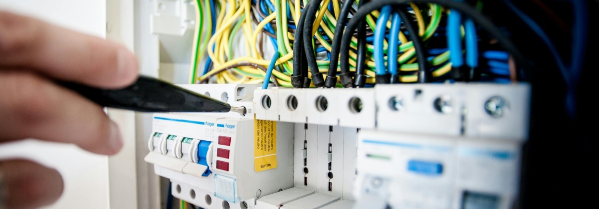
The service panel, often referred to as the electrical panel or consumer unit in the UK, is the critical junction where the mains electricity supply divides into subsidiary circuits while providing a fuse or circuit breaker for each circuit in a common enclosure. Usually, a service panel is fitted with a main switch to control the supply of the electrical power throughout the premises, and individual circuit breakers or fuses that protect each circuit.
A typical electrical service panel will divide electrical power among circuits, which then distribute it through conductors for protection to various areas of a building. The capacity of the service panel is measured in amperes, which denotes the maximum current it can safely handle without overheating.
Circuit Breakers and Fuses
Circuit breakers and fuses are integral components of the circuit protection system within the electrical panel. These safety mechanisms disconnect the electrical supply in case of overload or fault conditions, thus preventing potential hazards such as fires or electrical damage.
- Circuit breakers: These are automatic protection devices that can be reset after interrupting the current flow in a circuit in the event of an overload. In the UK, circuit breakers are commonly found in modern homes and are grouped into the circuit breaker panel, which may be a part of the main service panel or a separate sub-panel.
- Fuses: An older form of circuit protection, fuses contain a wire element that melts when current exceeds a specific threshold, effectively breaking the circuit. Fuses need to be replaced after they have operated, in contrast to circuit breakers, which can be reset.
Both circuit breakers and fuses are rated for specific amperages, and it’s vital to use the proper rating to match the conductor’s capacity for protection and the expected load of the electrical circuit. Proper selection and installation should align with the 17th Edition of the IET Wiring Regulations (BS 7671) to assure safety and compliance.
Wiring Installation Techniques
In the realm of residential electrical systems, proper wiring installation techniques are vital for safety, efficiency, and compliance with regulations. Electricians must adopt appropriate methods to lay out wiring alongside understanding the common circuits used in homes.
Cable Laying Methods
When laying cables, electricians should adhere to several key practices. The method of wiring must take into account the structure of the building and the materials used within its construction. For instance, raceway wiring systems protect wires with enclosed conduits, suitable for areas where cables may be exposed to potential damage. Alternatively, in tunnel wiring circuits, cables are run through tubes within the walls, which provides protection and a cleaner finish.
The forms of wiring system include several historical and contemporary methods:
- Concentric wiring involves wrapping strands of conductor wire with layers of insulation and protective materials, often used in historical buildings.
- Unprotected wiring is not commonly used due to the obvious risks, but it may still be found in some older installations and must be approached with caution.
- Aluminium wiring, once a popular economical option, presents challenges such as expansion and should be replaced or retrofitted with proper connectors for safety.
Common Residential Wiring Circuits
Residential buildings typically utilise a range of standard wiring circuits designed for specific applications:
- Building wiring generally includes a mix of ring and radial circuits supplying power to outlets and fixtures.
- Doorbell wiring is a low-voltage system often separate from main power circuits.
- Power wiring systems are responsible for delivering electricity to heavy-demand appliances and typically require dedicated circuits.
Particular circuit designs are employed to achieve specific functionalities in the home:
- Tunnel Wiring Circuit: Protects wiring in high-traffic areas or where long wiring runs are necessary.
- Staircase Wiring Circuit Diagram: Utilises 2-way switches to control lighting from two different locations.
- Godown Wiring Diagram: This configuration allows for sequential lighting control, ideal for warehouses or storage areas.
- Hospital Wiring Circuit: Designed to handle a complex array of switches and fixtures required in healthcare settings.
- Hotel Wiring Circuit: Similar to hospital circuits, with added emphasis on guest control and convenience.
For each of these circumstances, choosing the proper switch types, like 2-way switches, and understanding their wiring diagrams are imperative. Electricians should ensure all configurations comply with domestic wiring regulations to guarantee both safety and functionality.
Outlet and Switch Installation
Proper installation of socket outlets and switches is vital for the safe and efficient use of electrical devices in residential buildings. Electricians must adhere to the applicable BS 7671 Wiring Regulations to ensure that every metal wiring device is correctly installed to prevent hazards.
Types of Outlets:
- Standard Outlet: Typically used for general purposes in living areas and bedrooms.
- Special Outlet: Designed for heavy-duty appliances or specific rooms like bathrooms and kitchens.
Here’s a step-by-step guide for installation:
- Safety First: Ensure the mains power is off before beginning any work.
- Outlet Box: Mount the outlet box at the standard height of 450mm from the floor to the centre of the box.
- Wiring: Strip the wires, ensuring not to damage the metal conductors. Connect them to the socket outlet based on the manufacturer’s instructions.
- Earthing: Connect the green-yellow earth wire to the earthing terminal, crucial for preventing electric shocks.
Switches control the power supply to socket outlets and are usually found alongside or above them. They come in single pole, double pole, and more complex configurations for large rooms or staircases.
Installation Tips for Switches:
- Mount the switch plate at the UK standard height of 1200mm.
- Wire the switch in series with the load it controls, ensuring the live wire is interrupted by the switch mechanism.
When working with metal wiring devices, such as metallic switches or socket outlets, it’s imperative to properly earth the metalwork to protect against electrical faults.
Lastly, test all connections with a multimeter before restoring power to ensure everything is correctly and safely installed.
Lighting and Appliances
In the context of residential buildings, the electrical wiring for lighting and appliances is critical, supplying power to light fixtures and enabling the operation of major household appliances. This section meticulously examines the specifications for both.
Light Fixtures and Light Control
When installing light fixtures, electricians must consider Lighting Branch Circuits designed to supply electric light to an area or room. Each fixture’s connection is typically made at lamp holders and must provide both mechanical support and electrical connections. Light control, on the other hand, allows residents to manage the illumination levels within their homes and may involve dimmers, switches, or smart control systems that require careful planning to ensure compatibility with the light fixtures they operate.
Recommended Light Control configurations:
- Standard wall switches for simple on/off functionality
- Dimmer switches for adjustable light levels
- Smart switches for remote control via mobile apps
Major Appliance Electrical Requirements
Major appliances such as ovens, refrigerators, and washing machines draw significant power from the electrical systems. It is essential to adhere to the specific electrical requirements and wiring regulations set out in BS 7671, ensuring that each appliance is connected to an appropriately rated circuit. Electricians must assure correct voltage and amperage provision to prevent electrical faults and ensure safety.
Key Appliance Electrical Requirements:
- Dedicated circuits for uninterrupted power supply
- Proper cable sizes to handle the electric load
- Ground fault circuit interrupters (GFCIs) for safety in wet areas
By complying with these guidelines and considering the electrical capacity of the home, electricians can provide a reliable and safe electrical wiring system for both lighting and household appliances.
Understanding Wiring Diagrams
Electricians must have a thorough understanding of wiring diagrams to ensure the safe and efficient installation and maintenance of electrical systems in residential buildings. Wiring diagrams are visual representations of an electrical system’s components and their connections.
Electrical Wiring Installation Tutorials often begin with deciphering these diagrams. It’s imperative that one recognises the importance of different symbols, such as those for outlets, switches, and fixtures. These symbols provide electricians with the necessary information to identify the components and understand their placements within the circuit.
Typically, wiring circuit diagrams display the following elements:
- Power source: The origin of the electrical supply.
- Conductors: Represented by lines to show the path electric current flows.
- Switches: Symbols indicating control points that interrupt or direct the flow of electricity.
- Devices: Including appliances or fixtures which utilise the electricity.
A wiring diagram can be presented in various forms. For example, a simple room electrical wiring schematic details the connections and layout specific to one area, showcasing how the wiring is distributed across different electrical devices.
One may encounter several types of electrical diagrams:
- Single-line diagrams: Offer a broad overview of the electrical circuits.
- Pictorial diagrams: Showcase the physical layout and appearance of components.
Grasping the details of a wiring diagram ensures that the electrician can install and troubleshoot the system meticulously and safely. Through meticulous reading and interpretation of these diagrams, one can efficiently navigate the complexity of residential wiring, resulting in high-quality, reliable installations.
Troubleshooting and Maintenance
In addressing the essentials of troubleshooting and maintenance for electrical wiring in residential buildings, electricians must prioritise safety and adherence to standards set by the National Fire Protection Association. This section delves into key methods of identifying electrical issues and establishing routine system checks.
Identifying Electrical Issues
Insulation Damage: Electricians should meticulously inspect wiring insulation for any signs of wear, including cracks or brittleness, which could lead to dangerous short circuits or electrical fires. To determine insulation integrity, using tools like megohmmeters can reveal the insulation resistance, a key indicator of its condition.
Current Capacity and Tensile Strength: It’s critical that wires possess the required tensile strength and are fit to handle the anticipated current capacity. One must verify that wiring specifications match the electrical demands and that they are not subjected to mechanical stress beyond their tensile limits, as this could lead to significant damage or failure.
Protection from Moisture: Electrical systems must be reviewed for their resistance to moisture. All outdoor or bathroom circuitry should have the correct IP rating to prevent moisture ingress, which can be the root cause of many electrical issues in residential settings.
Routine Electrical System Checks
Electricians should conduct systematic inspections of the entire electrical system, ensuring:
Circuit Breaker and Fuse Assessment: Regular testing and examination of circuit breakers and fuses can prevent overloading and are vital for interruption in case of faults.
- Check for correct installation and function
- Ensure they match the circuit’s current rating
Earthing and Bonding Tests: All circuits must be correctly earthed, and cross bonding must be in place to provide protection from electric shocks and to facilitate the safe operation of protective devices.
- Confirm continuity of the main and supplementary bonding
- Inspect earthing systems for corrosion or loose connections
By adhering to these protocols and conducting thorough inspections, electrical wiring systems can be maintained in optimum condition, reducing the risk of faults and ensuring the safety of residential occupants.
Costs and Budgeting
When planning for residential electrical wiring, accurately assessing costs and budgeting effectively are crucial. It ensures that electricians can deliver a project on time and within the financial constraints set by their clients.
Estimating Material Costs
Material costs vary depending on the quality and the requirements of the electrical project. Electricians must consider the type of wiring, outlets, switches, and additional materials like conduits and fittings. For a typical household, cable prices can be significant, and it is wise to source materials that balance cost with reliability. Prices can fluctuate, so staying updated with suppliers’ pricing or purchasing in bulk might offer cost savings. The choice of materials should be made carefully to maintain safety standards while controlling expenses.
Labour Costs and Time Management
Labour cost is a critical part of any residential wiring project, often dictating project timelines and efficiency. Electricians should provide accurate labour estimates based on the size and complexity of the installation. For example, a typical three-bedroom house might take approximately 6-10 days to rewire, influencing the overall labour costs. To provide accurate figures, electricians use past project data or standard industry rates. As per current estimates, the cost to rewire a house in 2024 is varied, with factors such as property size and accessibility affecting the total labour costs. Time management is integral, as delays can inflate costs. Electricians should schedule tasks efficiently, allowing for unforeseen delays without compromising the project’s budget.
Regulatory Compliance and Inspections
In the UK, the compliance with building codes and electrical codes is imperative for electricians working in residential buildings. Inspections by the building control authority ensure that electrical installations meet the IET BS7671 Wiring Regulations. These rules are designed to safeguard occupants by dictating the standards for design, installation, and maintenance of electrical systems.
During construction or renovation, regulatory compliance begins with the submission of detailed plans to the local building control authority. It is their responsibility to review these plans against the current Building Regulations for England and Wales, ensuring all safety and energy efficiency measures are in place.
| Stage of Work | Compliance Responsibility | Authority Inspection |
| Design | Electricians/Designers | Building Control Authority |
| Installation | Electricians/Businesses | Building Control Authority |
| Post-installation | Testing by Qualified Electricians | Building Control Authority |
The Energy Market Authority also plays a role by regulating electrical standards, which include the safety of the energy supply to homes. After installation, electricians must conduct mandatory tests, such as Fixed Electrical Inspections. An Electrical Installation Condition Report (EICR) is then produced, outlining any deviations from the national safety standards and suggesting necessary rectifications.
Compliance is not just about meeting legal requirements; it is about ensuring the longevity and safety of electrical installations. Knowledge and adherence to regulations by electricians are, therefore, non-negotiable in the pursuit of professional excellence and public safety.

